Share this
by PowerShield on Dec 15, 2021 9:45:02 AM
Introduction
As mentioned in Part 1 of this series, we know that Ohmic measurement values are useful for trending life and detecting faults in lead acid batteries. We also know from Part 1 that different tools may produce different readings for the same battery, so interpreting a reading has to be done with sufficient knowledge of the factors which can influence a reading. A question that is sometimes asked when trying to determine the initial reference (known as the baseline) is whether the internal resistance value (Ri) from the datasheet can be used.
This is a logical question as the Ri is expressed typically in mΩ or µΩ, which is the same unit of measure as impedance. However, the short answer is NO, because the battery is not a simple resistor but an electrochemical device, therefore the measurement result is dependent on the technique used.
To take a measurement a change in voltage has to occur on the battery. This change can be induced by the test equipment or the power system itself. The measurement value of a battery is dependent on the rate of change and amplitude of the stimulus applied. That is why different battery testers may produce different readings for the same battery. It also makes it difficult for battery manufacturers to specify an impedance or internal ohmic value for a battery, as they would need to list a number of values for the different testers on the market.
Let’s look into the details of the internal resistance measurement that produces the Ri battery datasheet parameter.
Internal Resistance Measurement
There is an industry standard for measuring a battery’s Ri for VRLA batteries which is defined in EN 60896-21 “Stationary lead-acid batteries - Part 21: Valve regulated types - Methods of test”. This measurement technique requires that the battery voltage is measured for two short discharges for a specified period with a 5-minute resting period in between. The first discharge produces V1 using I1and the second V2 using I2.
The formula for Internal Resistance is 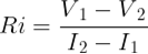
Measurement sequence:
- First discharge (I1) is 20 seconds with a magnitude of 4 x I10
- Rest battery for 5 minutes
- Second discharge (I2) is 5 seconds with a magnitude of 20 x I10
Example for an 100Ah battery with an I10 of 10 A the test currents are 40 A (4 x I10) and 200 A (20 x I10).
As you can see, based on the magnitude of the test currents and the overall duration of the measurement, this method is not intended for use in the field. Instead, this method is intended to be used by battery manufacturers to produce a value of Ri for the datasheet in a defined manner, so that it can be compared to other batteries.
Impedance Measurement
There is no industry definition for a battery impedance (internal ohmic value) measurement -each equipment manufacturer has their own ‘recipe’. One example is the Hioki battery tester BT3554, which uses a test signal current of 160mA for measurements in the range up to 30mΩ and a duration of 1 second.
The expectation based on the theory is that the different measurement techniques will produce different values so let’s do an experiment to see what the difference could be.
Experiment
Measure a battery with two different methods.
Equipment:
- Fluke 179 Multi meter, Fluke 36 Current meter, constant current load
- Panasonic LC-V1233P, 33Ah valve regulated lead acid battery
The I10 current for the Panasonic 33Ah battery is 3.1 A.
I1 = 4 x I10 = 4 x 3.1 A = 12.4 AI2 = 20 x I10 = 20 x 3.1 A = 62.0 A
First discharge of 20 seconds with 12.4 A, end battery voltage is 12.09 V.
Then a 5-minute resting period.
Second discharge of 5 seconds with 62.0 A, end battery voltage is 11.42 V.
![]()
Measurement with the Hioki Battery Tester is 7.1 mΩ and 12.71 V.
So, the Ri method produces 13.5 mΩ and the Hioki method produces 7.1 mΩ for this Panasonic 33Ah battery.
Conclusion
From the above we can see that Ri and impedance (internal ohmic value) are not the same. We can conclude that these parameters cannot be interchanged because they are different. It is therefore not appropriate to use the Ri value from the battery datasheet as the baseline.
For further insights into the topic of impedance measurement, explore the other articles in the series:
Battery Internal Ohmic Measurements Explained – Part 1 (Impedance)
Battery Internal Ohmic Measurements Explained – Part 2 (Kelvin Connection)
Battery Internal Ohmic Measurements Explained – Part 3 (Importance of Context)
If you have any questions about PowerShield8 and Link battery management software, don’t hesitate to contact us. You can also sign up for our newsletter here.
Share this
Battery Cabinets vs. Battery Racks
Battery replacement intervals