.png)

This is the eighth in a series of units that will educate you on the part played by a battery in an uninterruptible power supply (UPS) system.
IEEE Standard 1187 establishes the recommended practices for the design and installation of valve-regulated lead-acid (VRLA) batteries. The purpose of this paper is to highlight the most significant considerations identified in that standard, including:
- Safety considerations
- Design consideration
- Receiving and installation procedures
IEEE 1188, which was discussed in Unit 8, describes the procedures for acceptance (commissioning) tests, including
- Pretest requirements
- Test procedures
- Corrective actions
In general, work on batteries should only be performed by knowledgeable personnel who have proper training/certification, proper tools, and personal protective equipment (PPE). IEEE Standard 1657 establishes minimum curriculum for battery technician certification. Prior to any task involving contact with a battery, a job hazard analysis should be conducted to identify any potential hazards that might be encountered.
Safety considerations
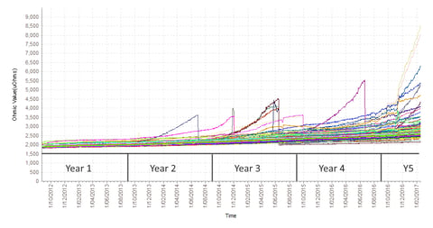
HAZARD NOTIFICATION - Proactive notification of an impending failure is far better than reactive alarms after a failure has occurred. Continuous (real-time) monitoring is an indispensable tool that, when properly used, can detect and predict failures before they turn into fires, melt-down, arc flash, or other catastrophic failures. Battery monitoring should always be installed by certified technicians, preferably prior to commissioning.
SHOCK HAZARD - Because most UPS system batteries are rated for greater than 50 Vdc, electrically-rated and/or insulated gloves should be worn. Energized parts, such as terminal posts and intercell connections, should be insulated or shielded; shields should be removable when a section of the battery is being serviced.
GROUND FAULT DETECTION - GFD is recommended (or may be required by code) for most battery systems, depending upon the grounding method used. Refer to local codes or IEEE 1187 for guidelines. The UPS design will usually dictate the type of grounding.
ARC FLASH - Arc flash is an explosion of heat, light, and pressure. For voltage above 100 Vdc, the hazard is reduced if there is at least 305 mm (12 in) of space between potentials. Below that, exposed parts should be protected. Arc flash PPE below 100 Vdc is not required unless dictated by local code. Above 100 Vdc, arc-rated clothing should be worn.
CHEMICAL HAZARDS – The electrolyte in lead-acid batteries consists of approximately one part sulfuric acid to two parts water. Electrolyte is immobilized in VRLA batteries, thereby minimizing (but not eliminating) risk of contact. A neutralizing agent (such as baking soda) and portable eye wash should be on hand. Contact with eyes or mucus membranes is very dangerous. PPE should include acid resistant gloves and clothing as well as safety glasses.
THERMAL HAZARDS - The greatest thermal hazard is flash burns associated with short circuit or arc flash. Thermally-rated or arc-rated gloves should be worn.
LIFTING AND HANDLING HAZARDS - PPE lifting tools and techniques appropriate to the task should be used. Consult the battery manufacturer for recommended material handling slings or lifts.
PPE - Consult local codes or IEEE 1187 for a list of recommended PPE, which will include specifications for arc and chemically rated clothing, gloves, safety glasses, shoes, aprons, and insulated tools.
Design considerations
Decisions about the location and space for battery systems should be made well in advance of delivery. Considerations include space for personnel and handling equipment, floor loading, ventilation, heating and cooling, PPE availability, spill containment (if required), and illumination. Consult local codes or IEEE 1187 for guidelines.
MAINTAINABILITY - Terminals of all cells or units should be easily accessible during normal float operation for routine maintenance and inspection, as described in Unit 8. Avoid installations containing series-parallel connections within a string. Ensure proper alignment and spacing of cells/modules for ventilation, use of lifting devices, and structured cabling.
SEISMIC - Battery racks and cabinets should be designed for identified seismic categories. Racks are typically identified with a seismic rating, and are usually bolted to the floor. Cabinets are often installed on raised floor, so they must be anchored to the sub-floor where necessary. Cabinet doors should be secure to prevent popping open during an earthquake. Racks should be assembled in such a way that they are not rigidly connected at multiple horizontal and vertical points. Batteries need to sway without breaking intercell connections and without sliding off the rack or shelf. Rack or cabinet manufacturers should provide the applicable installation instructions.
HEATING, VENTILATION AND AIR CONDITIONING (HVAC) - As discussed in previous units, temperature management is a particular concern for lead-acid batteries. The ideal temperature is between 20 °C to 25 °C, measured at the negative terminal post of designate pilot cells. VRLA cells – especially those enclosed in a cabinet - typically operate at temperatures above ambient. Conversely, operating in cold temperatures can have a negative effect on performance. There should be no temperature differential greater than 3 °C (5.4 °F) between cells within a battery system. Batteries should be placed so there is no spot heating or cooling, and no stratification between bottom and top racks or shelves. Cells/units must be placed to allow sufficient air flow on all sides.
HAZARDOUS GAS - Because VRLA cells are more sensitive to thermal runaway than VLA cells, which can happen fairly quickly, continuous temperature monitoring is recommended. When a VRLA cell overheats it opens a pressure release valve that vents hydrogen and oxygen into the space. This can be a momentary “burp” or a continuously open condition, depending upon the temperature and charge current. The rate of hydrogen evolution can be predicted. IEEE 1635/ASHRAE 21 standards provide engineering guidance for the design of HVAC to prevent accumulation of hydrogen above the maximum allowed by code. The lower flammability level (LFL) is 4% of the air. The safety margin is typically half of that volume. Consult local codes for the maximum allowable concentration of hydrogen at anticipated temperatures and altitude.
BATTERY PROTECTION – Detailed guidelines for battery protection are provided in IEEE Standard 1375. Briefly summarized, dc-rated fuses or circuit breakers should be located as close as practical to the end of a battery string. Not all circuit breakers are rated for ac and dc applications; for those that are, the dc ampere rating is always lower than the ac rating. When strings are connected in parallel, ideally every string should be individually protected. Parallel strings can cause increased short-circuit current when a fault is downstream of the common dc bus. Size string conductors to compensate for additional current if one or more of the strings are taken offline for maintenance or due to failure.
Receiving and inspection
INSPECTION - Visually inspect every package for apparent damage and electrolyte leakage and note any discrepancies on the bill of lading. Keep records for future reference and warranty claims.
UNPACKING AND HANDLING - Never lift or handle cells by the terminal posts, bus work or cables; instead use proper lifting equipment per the manufacturer’s guidelines. Reject any cells with visible defects such as leaks, loose terminal posts, or cracked containers.
ASSEMBLY - Assemble all racks, enclosures and modules following the manufacturer’s recommended procedures.
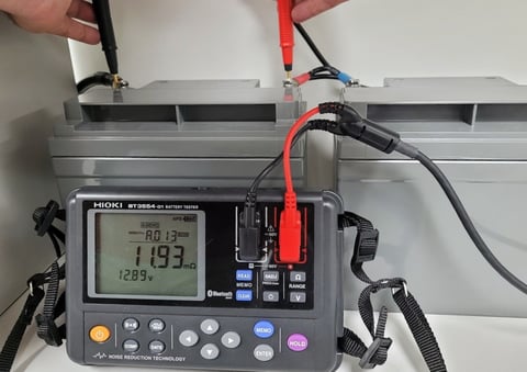
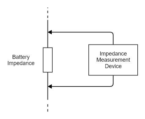
CELL/MODULE INSTALLATION – Prior to installation, measure the open circuit voltage of every cell to verify that there is no more than 0.1 Volt difference from the manufacturer’s published value. Report any discrepancies to the manufacturer before proceeding. Also measure internal ohmic values. When significant variation is noted, follow recommendations of IEEE 1187. Install cell units as appropriate for the installation, clean when necessary. Connect and torque connections per manufacturer’s requirements. Verify proper positive-to-negative connectivity throughout the battery. Read the voltage of the complete battery; recheck connections if it is less than expected. Mark each cell/module with identification. Read and record interconnection resistance.
FRESHENING CHARGE - Charge the battery to recover capacity that may have been lost during shipping and storage, following manufacturer’s instructions regarding voltage, charge current limit and duration.
Testing and Commissioning
Acceptance testing of a battery should be performed at the place where it is assembled. For example, pre-configured battery cabinets should be acceptance tested at the factory or upon initial installation. The purpose of an acceptance test is to confirm that the battery meets the specified discharge rate and duration.
Some batteries are not fully formed until they have been in service for several months. That means that, unless 100% capacity upon delivery was specified, the battery might perform at as much as ten percent below its nominal capacity during acceptance test. IEEE 1188 describes a time-adjusted calculation, running the full published rate. It also describes the procedure to be followed for pretest and acceptance test.
Throughout the life of the battery, all measurements will be compared to the base line established during the acceptance test.